A Primer in Basic Electrical Troubleshooting, Part II: Using a Multimeter

Learn how to use a multimeter for automotive electrical troubleshooting, from testing devices directly to tracing circuit faults step by step.
Let me tell you a story about the first time I chased an electrical gremlin on my own car. I was convinced the problem was somewhere deep in the wiring, buried under three layers of carpet and thirty years of good intentions. I had a wiring diagram spread across the passenger seat, a flashlight in my teeth, and absolutely no plan. Two hours later I found a corroded connector about four inches from the device itself. If someone had just walked me through a logical sequence, I could have found it in ten minutes and saved myself a very bad afternoon.
That's what this is. A logical sequence. Last week we talked about what automotive electrical circuits actually are and how they can fail. This week is about picking up a tool and going to work.
Start Before You Touch the Multimeter
The very first question you need to answer is whether the device itself has failed, or whether the rest of the circuit is the problem. The device could be a bulb, a fan motor, a washer pump, anything with a job to do. Before you trace a single wire, you need to know if the part itself is still good.
The most direct way to find out is to temporarily wire the device straight to the battery. Grab two lengths of wire, connect them to the device however you need to (quick-connect terminals, wire nuts, alligator clips, whatever gets the job done), and briefly touch the other ends to battery positive and negative. If the fan spins or the bulb lights up, the device is fine and your problem is somewhere else in the circuit. If nothing happens, you need a new part, and you can stop pulling your hair out over the wiring.
On cars that have duplicate devices, like brake lights or turn signals, there's an even faster version of this test. If the left brake light works and the right one doesn't, swap the bulbs. If the dead side follows the bulb, it's the bulb. If the dead side stays put, it's the wiring. Thirty seconds, no tools, no guesswork.

Look Before You Measure
So the device is good. Now where do you go? A lot of people jump straight for the wiring diagram, but here's the thing: on most vintage and older cars, wiring diagrams are genuinely hard to read, and the fault is almost never in the middle of a wire anyway. It's almost always at a connector.
Before you do anything else, look. Pull the connectors off the device and any other components in the circuit and actually examine them. Is there corrosion on the terminals? Is a wire broken off at its crimped end? Is a connector only half-seated? On any car that's spent time near road salt or high engine heat, this kind of thing is astonishingly common. Fix what you find, test the circuit again, and you may be done before you ever touched a meter.
While you're at it, check the fuse. Don't just look at it. If it's an older ceramic-body fuse, squeeze the tabs and rotate it in the holder. The tips corrode over time and the connection goes intermittent without the fuse ever looking blown. Pull it, clean the tips if needed, reseat it firmly.
Now Pick Up the Multimeter
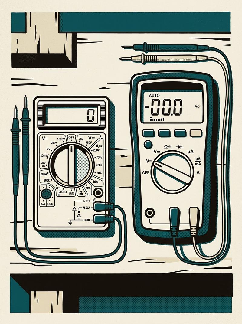
If you've done all of the above and the circuit still isn't working, it's time to actually measure something. If you don't own a multimeter, go buy one today. A very cheap one is better than nothing, but I'd push you toward spending around twenty-five to thirty dollars on one that has three specific features.
First, auto-ranging. An auto-ranging meter figures out the scale of what you're measuring on its own. You can spot one immediately because its rotary dial has half the number of positions as a manual-range meter. You want this because when you're under a dash with a flashlight in one hand, the last thing you need is to stop and re-select a range every time you move the probe.
Second, an audible continuity beep. When you're measuring resistance and the value drops near zero (meaning current can flow freely through that section of the circuit), the meter beeps. This matters more than it sounds. When you're probing around with both hands occupied and your head stuffed under a dashboard, being able to hear the answer without looking at the screen is genuinely useful.
Third, full-sized probe sockets. Most professional-grade and mid-tier meters use the industry-standard 4mm banana plug sockets. Cheaper pocket meters often use 2mm sockets. This matters because one of the most valuable accessories you can buy is a probe lead kit with interchangeable tips, including alligator clips. The ability to clip your ground probe to a chassis ground point and leave it there while you work with the positive probe frees up a hand and makes the whole process dramatically easier.
What You're Actually Measuring
A multimeter does a few things. In the context of basic automotive troubleshooting, you're mostly doing three of them.
Voltage is what you check when the circuit is live. You're asking: is power actually arriving at this point? Set the meter to DC voltage, clip or hold the negative probe to a known good ground (the negative battery terminal is always a safe bet), and touch the positive probe to the point you want to check. On a healthy 12-volt circuit, you should read close to battery voltage, usually somewhere between 12 and 14.5 volts depending on whether the engine is running. If you read zero at a connector that should be hot, power isn't making it there. If you read battery voltage all the way to the device and the device still doesn't work, the problem is either the device itself or the ground side of the circuit.
Continuity is what you check when the circuit is unpowered. You're asking: is there an unbroken electrical path between these two points? Set the meter to its continuity or resistance setting (the one that beeps), disconnect the circuit from power, and probe both ends of whatever section you're testing. A beep means the path is complete. Silence means there's a break somewhere between your two probe tips. This is how you find that one wire that looks fine on the outside but has a broken conductor inside the insulation.
Resistance is closely related to continuity, but it gives you a number. A ground connection that tests as continuous might still have enough resistance to starve a component of current. A good ground should read very close to zero ohms. If you're seeing a few ohms on what should be a clean ground path, clean those connections.
Work from the Device Outward
The most efficient way to use a multimeter in circuit troubleshooting is to start at the device and work backward toward the power source. Check for voltage at the device's connector first. If it's there, your wiring is fine and you've confirmed the device is the problem (consistent with your earlier direct-battery test). If it's not there, back up one connector and check there. Keep going until you find the point where voltage exists on one side but not the other. That's your fault location, and it's usually a bad connection, a failed relay, or a blown fuse you missed on the first pass.
None of this is magic. It's just a sequence. The cars that used to defeat me for hours were the ones where I skipped steps, assumed I knew where the problem was, and started pulling things apart based on a hunch. Work the sequence. Battery test the device. Look at the connectors. Check the fuse. Then measure. Most of the time you won't even make it to the multimeter, because the problem is sitting right there in plain sight, waiting to be found by someone who remembered to look first.
Written by
Joshua Hawkins